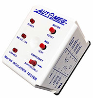
Automeg Automatic Insulation Testers
Special Controls
When power is applied, the power LED comes on. When a motor start signal is applied to pin 3, the middle LED comes on, showing that the 500 VDC is being applied to the motor winding. If the winding is good, the Automeg completes the megging operation, and the motor starts signal is then connected from pin 3 to 4.
If the winding is bad, the Low Meg LED comes on, and the motor start signal will not be available at pin 4 to engage the motor starter. To unlatch the Low Meg alarm contact, depress the Motor Reset pushbutton. The Low Meg Alarm contacts, pins 10 and 11, are a normally open relay contact that closes upon the Low Meg Alarm condition.
An Emergency Bypass Switch is provided to bypass the megging process. Placing this switch in the bypass mode disables the megging circuit, and engages the motor start relay circuit, pins 3 and 4.
The Meg Test Button is used to verify that the Automeg unit will provide an indication for a Low Meg condition should the condition occur.
The Meg test is used to check the low Meg condition when there is no start signal applied. If the start signal is present, the Meg test circuitry is disable.
Item # |
Item Name |
Alternating Current (AC) Input Voltage |
Frequency |
Current |
List Price |
Add To Cart/Request Quote |
|---|---|---|---|---|---|---|
| AUTOMEG /Asset/a1749.jpg | N/A Automeg Automatic Insulation Tester | Alternating Current (AC) Input Voltage N/A 120 V | Frequency N/A 50 to 60 Hz | Current N/A 5.9 V·A | Quote |
Add To Cart
Request Quote |


